WelderDestiny › Welding Engineering Tools › Dissimilar Metals Welding
Dissimilar Metals Welding
Performing dissimilar metals welding is a common occurrence, especially when dealing with applications where advanced alloys are needed due to the mechanical, physical or corrosion properties that the components will need to exhibit.
The WelderDestiny Compass: Weekly e-zine Subscription
You can take a look at "The WelderDestiny Compass" back-issues by clicking here.
Due
to economic factors, different metals give optimum performance in different
parts of a system. They do however need to be joined to each other. When
welding is the best joining technique, then our dissimilar metals welding problem
raises its head.
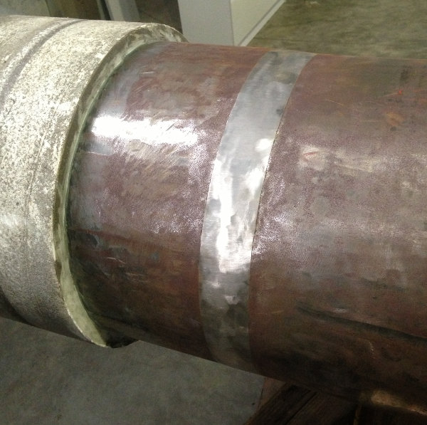
 Carbon Steel Pipe With Stainless Steel Internal Cladding - Welded With Nickel Based Filler - The Surface is Ground Smooth to Assist Ultrasonic Testing.
Desired Dissimilar Metals Welding Outcomes
When
joining two different metals by fusion welding, we are melting together three
different constituents:
- Base metal 1
- Base metal 2
- Welding filler metal. (In some instances, no filler metal is added. This is called autogenous welding)
When
performing dissimilar metal welds, we are interested in the following final
outcomes:
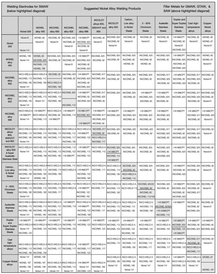
- That the weld metal composition formed is stable from a metallurgical point of view: Some metal compositions will form brittle intermetallic phases, or some metals will quite simply not mix. Obviously such compositions are to be avoided. The simplest way of avoiding this is to use combinations that have been used successfully before. This can simply be done by looking up suitable filler metals for different base metal combinations from existing tables. These are freely available on the internet from most filler metal suppliers. See Figure 1 below for an example recommended filler metal table from "Special Metals".
 Figure 1: Dissimilar metals welding recommended filler table. This table comes from a "Special Metals" catalogue. They produce the industry standard "Inconel" branded nickel based filler metals, hence the emphasis on these consumables in the table.
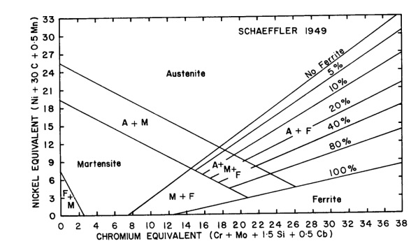
- That the weld metal formed has a microstructure that provides us with the necessary mechanical properties: Even if we are using a filler metal recommended in a table, we may still end up with a microstructure that is not suitable for our specific application. It is therefore important to establish what the microstructure is going to be, to be able to choose the best filler metal from a selection of different materials. The best way of doing this for the typical combinations of base metals is to use the Schaeffler diagram. See Figure 2 below for an example of a Schaeffler diagram. (Lower down the page we will go into the details of how to use and interpret this diagram when performing dissimilar metals welding.)
 Figure 2: Schaeffler Diagram - Used in dissimilar metals welding to predict the weld metal composition and properties.
- Any possible difficulties we may have during the welding process: Certain types of weld metal may pose different challenges during the welding process. So for instance, a 100% austenitic weld metal is prone to suffer hot cracking, while a martensitic weld metal is prone to be brittle and suffer from hydrogen assisted cold cracking. (HACC) By understanding the composition and structure of the weld metal, we can try to prevent any such problems. Once again, the Schaeffler diagram comes in handy for this purpose.
Using The Schaeffler Diagram
To
most easily explain the use of the Schaeffler diagram for dissimilar metals
welding, I will explain the use and show it as an example at the same time.
Let us assume that we will be welding the following materials:
- A carbon steel: Designated "Parent metal 1", with chemical composition of: C:0.25%; Si:0.3%; Mn:1%
- To a duplex stainless steel: Designated "Parent metal 2", with a chemical composition of: C:0.03%; Si:0.6%; Mn:1.5%; Cr:22%; Mo:3%; Ni:5%
- Using a duplex stainless steel filler: Designated "Filler metal" with a chemical composition of: C:0.02%; Si:0.5%; Mn:1.5%; Cr:23%; Mo:3%; Ni:9%. - Note that this filler metal is not listed in the "Inconel" table above, but is often used when joining these materials.
To
use the Schaeffler diagram, the following steps need to be taken:
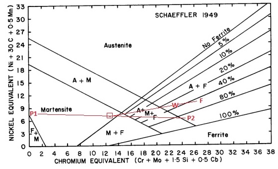
- Calculate the Chrome and Nickel Equivalents for parent metal 1. (Cr Equivalent = 0.45; Ni Equivalent = 8 – Calculate these by applying the Cr and Ni equivalent formulas shown on the axes of the Schaeffler diagram)
- Plot the point on the diagram. (See P1 on the diagram below.)
- Calculate the Chrome and Nickel Equivalents for base metal 2. (Cr Equivalent = 25.9; Ni Equivalent = 6.65 – Calculate these by applying the Cr and Ni equivalent formulas shown on the axes of the Schaeffler diagram)
- Plot the point on the diagram. (See P2 on the diagram below.)
- Draw a line between these two points. (See red line joining P1 and P2.)
- Based on the ratio of base metal melted from each of the two base metals, mark a position along the line. We are assuming a 15% dilution from parent metal 1 and 15% dilution from parent metal 2 and 70% dilution from the filler metal. Because the dilution of parent metal 1 and parent metal 2 are the same, the position we mark is exactly half way between P1 and P2 on the red line joining them. (See the red box on the line joining P1 and P2 in the diagram below.)
- Calculate the Chrome and Nickel Equivalents for the filler metal. (Cr Equivalent = 26.75; Ni Equivalent = 10.35)
- Plot the point for the filler metal on the diagram. (See F on the diagram below.)
- Draw a line between the point identified on the P1 – P2 line (the red box) and the point for the filler metal. (point F) (See red line joining F and the red box in the diagram below.)
- Based on the ratio of metal melted from the parent metals and the filler metal, mark a position along this line. Assuming a 30% dilution from the parent metals and 70% contribution from the filler metal, we will plot this point 30% along the line from point F. (See the point marked W on the diagram below.)
- The point W on the diagram below is then the anticipated composition of the weld metal.
- Its location on the diagram also gives an indication of the microstructure that is anticipated, as well as how sensitive it is to dilution. In this case we see that it will be between 20 – 40% ferrite with the rest austenite. Because point W is relatively close to the austenite + martensite + ferrite line, we can see that it is relatively sensitive to dilution from the parent metal, so we would have an instruction on the welding procedure that low dilution welding techniques are to be used.
 Figure 3: Schaeffler Diagram Application Example
Some Notes to the Dissimilar Metals Welding Example
- The Schaeffler diagram is not very accurate for modern duplex stainless steel parent metals, because it does not take account of the effect of Nitrogen as an alloying element. It is however accurate enough for our purposes because the welding filler metals and weld metals are low in Nitrogen, so their positions are more accurate for weld metals than the parent metals.
- An Excel spreadsheet is available for performing these calculations automatically. This spreadsheet is freely available when you sign up to receive the free WelderDestiny newsletter. The spreadsheet also allows calculations to be performed for overlay welding. Click on the prominently displayed subscribe button to sign up for the newsletter.
- The fact that there is going to be quite a bit of ferrite in the weld metal (Around 20 - 40%) means that it will not be very sensitive to hot cracking. We will look at these issues in future web pages.
WelderDestiny › Welding Engineering Tools › Dissimilar Metals Welding
The WelderDestiny Compass: Weekly e-zine Subscription
You can take a look at "The WelderDestiny Compass" back-issues by clicking here.